Shijiazhuang Zhongqian Pump Industry Co., Ltd. · Slurry pumps / Spare parts / Technical support
ZQZhongqian PumpZHONGQIAN PUMP
TECHNICAL SUPPORT

Slurry Pump Technical SupportSelection · Installation · Service · Online reading

From selection and installation to operation, maintenance and troubleshooting, technical notes and documents are arranged in site-work sequence.

Based on the product manuals and established engineering practice. Charts, manuals and drawings are available to read online.

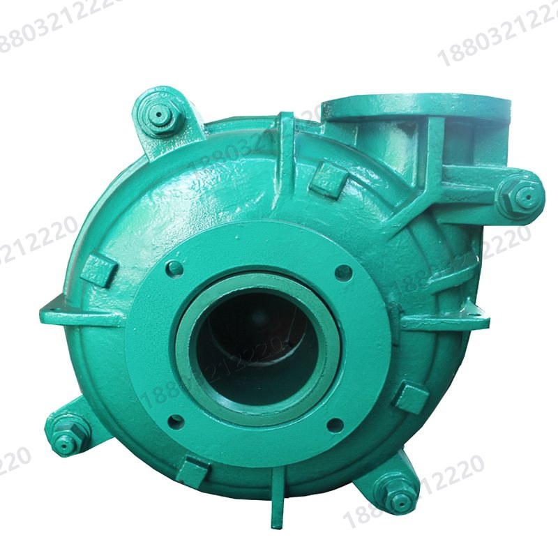
AH series pump head
Construction drawing
SELECTION

Selection procedure

Define the medium and system first, then the pump type, materials and seal.

01

Slurry profile

Define solids concentration, particle size distribution and maximum size, particle hardness and shape, slurry density, pH, temperature and entrained air. These determine wetted materials and passage geometry.

02

Hydraulic parameters

Establish normal, maximum and minimum flow Q and total system head H (static lift plus pipe and local losses), with sensible margin so the pump stays near its best efficiency point.

03

NPSH check

Ensure available NPSHa exceeds required NPSHr with a safety margin. Keep the suction line short, straight and free of unnecessary bends; use a flooded suction where needed.

04

Material matching

High chrome alloy for coarse abrasive particles, rubber liners for fine or mildly corrosive slurry, stainless or high-nickel alloys for aggressive chemistry. Mismatched materials are a leading cause of early failure.

05

Seal and drive

Choose packing, expeller or mechanical sealing to suit leakage limits; choose direct coupling, belt drive, fluid coupling or variable frequency drive to suit space and speed control.

06

Motor margin and life-cycle cost

Correct shaft power for slurry density and allow roughly 10-25% motor margin. Evaluate energy, wear-part consumption and downtime costs, not only the purchase price.

This section describes general slurry pump principles, selection and maintenance. It does not constitute a commitment regarding particular product parameters, materials, service life or scope of service. Binding values are those in the supplied documentation and in documents confirmed in writing by both parties.
PARAMETERS

Key parameters

Understanding chart fields is the basis for comparing models.

Flow Rate

Q

Slurry volume delivered per unit time, given in m3/h or L/s in the charts.

Head

H

Energy delivered per unit weight of liquid, in metres; related to speed and impeller diameter.

Speed

n

Shaft revolutions per minute; one model may have several performance ranges at different speeds.

Efficiency

η

Maximum efficiency and its duty point, listed as a percentage in the charts.

NPSHr

NPSHr

Required net positive suction head, used to assess suction conditions; given in metres.

Particle & Power

d / P

Maximum particle size in mm, allowable motor power in kW, and the motor model.

INSTALLATION & OPERATION

Installation, start-up and monitoring

Installation governs vibration and bearing life; operating data set the service timing.

Installation & start-up

01

Install the pump on a solid foundation capable of carrying its full weight and eliminating vibration; tighten all foundation bolts and support piping and valves independently.

02

Turn the shaft by hand in the direction of rotation; the impeller must move freely without rubbing. Check motor rotation against the arrow on the casing - reverse rotation is prohibited.

03

Align pump and motor shafts accurately for coupling drive; for belt drive keep the shafts parallel and square the sheaves to the belts.

04

Fit a removable spool in the suction line, long enough to remove the cover and replace wear parts during service.

05

For packing seals, open the sealing water before start-up, check flow and pressure, and adjust the gland for a drip leak. Sealing water pressure is normally above discharge pressure.

06

During operation check sealing water pressure and flow and bearing temperature regularly; flush the pump with clean water before stopping where possible.

Operating checks

Motor current

Current should stay stable. A sustained rise may indicate higher slurry density, a blocked impeller or rubbing; marked fluctuation suggests air ingress on the suction side.

Suction / discharge pressure

Abnormally high discharge pressure often points to a blocked line; a pressure drop may result from impeller wear or seal leakage. Read it together with the flow trend.

Bearing and motor temperature

Bearing temperature rise is a direct signal of lubrication and alignment condition. Too much, too little or emulsified oil, or loss of cooling water, all cause overheating.

Vibration and noise

Periodic knocking, cavitation noise or a step change in vibration usually indicates impeller imbalance, foreign objects, bearing wear or misalignment.

MAINTENANCE

Maintenance levels and service notes

Daily, weekly and monthly checks focus on seals, clearances and lubrication.

Daily inspection

Check flanges and seal leakage, foundation and coupling bolts; log current, pressure and bearing temperature; clean the suction strainer and watch sealing-water flow and leakage.

Weekly service

Check oil level and condition, coupling elastomers and seal flush pressure; measure vibration, re-align shafts and clean slurry build-up from the casing exterior.

Monthly / scheduled overhaul

Inspect wear on the impeller, front and rear liners and volute liner; check the shaft sleeve and seals; remove deposits, recheck level and tighten all fasteners. Keep a spare-parts log.

Service notes from the manuals

01

Shaft seal: check sealing water pressure and flow regularly, maintain a small flow of clean water along the shaft, adjust the gland and replace packing periodically.

02

Impeller adjustment: maintain a 0.5-1 mm clearance between impeller and front liner on metal-lined pumps; keep clearances to front and rear sheaths equal on rubber-lined pumps.

03

Bearing lubrication: inspect the bearing assembly and grease condition regularly, normally at intervals not exceeding 12 months. Excess grease causes bearing overheating.

04

Assembly: preheat bearing inner rings to no more than 120 C. Inner ring, outer ring and spacer of double row tapered roller bearings form a matched set and must not be interchanged.

05

Turn the shaft of a standby pump by a quarter turn each week so that the bearings share static load and external vibration evenly.

06

Performance falls as the impeller-to-liner clearance grows; readjust the impeller in good time and replace wear parts when the pump can no longer meet system demand.
TROUBLESHOOTING

Troubleshooting and safety notes

Isolate power and relieve pressure before any service work.

SymptomPossible CausesCorrective Action
Pump does not primeAir leakage at suction piping or packing; wrong rotation or damaged impeller; blocked suction lineSeal the leakage; check rotation and replace the impeller; clear the blockage
Bearing overheatingToo much or too little grease; contaminated grease; damaged bearingUse the correct amount of grease; replace the grease; fit a new bearing
Pump vibrationPump and motor shafts misaligned; bent shaft; internal rubbing or unbalanced impellerRealign the shafts; replace or clean the shaft; remove rubbing and replace the impeller
Leakage at the packingWorn packing; worn shaft sleeve; dirty sealing waterRenew the packing; replace the shaft sleeve; use clean sealing water
Packing overheating / high powerGland too tight; internal rubbing; over-tight drive belts; excessive flowLoosen the gland bolts; remove rubbing; adjust the belts; correct the operating duty
Noise / irregular runningDamaged bearing; unbalanced impeller; air ingress or blockage in suction; uneven flow or cavitationReplace the bearing; replace the impeller; remove air ingress and blockages; stabilise suction conditions

Safety notes

  • Ensure the shaft rotates in the direction of the arrow on the casing. During a motor test the motor must be fully decoupled from the pump - reverse rotation of the pump shaft is prohibited.
  • For packing-sealed pumps, install the packing as specified before start-up.
  • For mechanically sealed pumps, a sealing-water supply is mandatory; dry running is prohibited.
  • For oil-lubricated pumps, fill to the oil level mark before start-up; running without oil is prohibited.
  • Read the instruction manual and the manuals of all associated equipment before installation and use.
  • Isolate the power supply before installing or servicing the unit. Never reach into or remove guards while the unit is running.
  • Do not operate the pump for extended periods at low or zero flow, to avoid vibration or vaporisation of the liquid.
ONLINE READING

Technical documents

Performance charts, manuals and catalogues are available to read online.

Technical documents are available to read online. Binding values follow the supplied documents and written confirmation.
DRAWINGS

Drawings and reference sheets

Construction drawings, dimension sheets and reference covers; click to enlarge the notes.

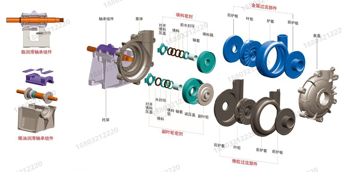
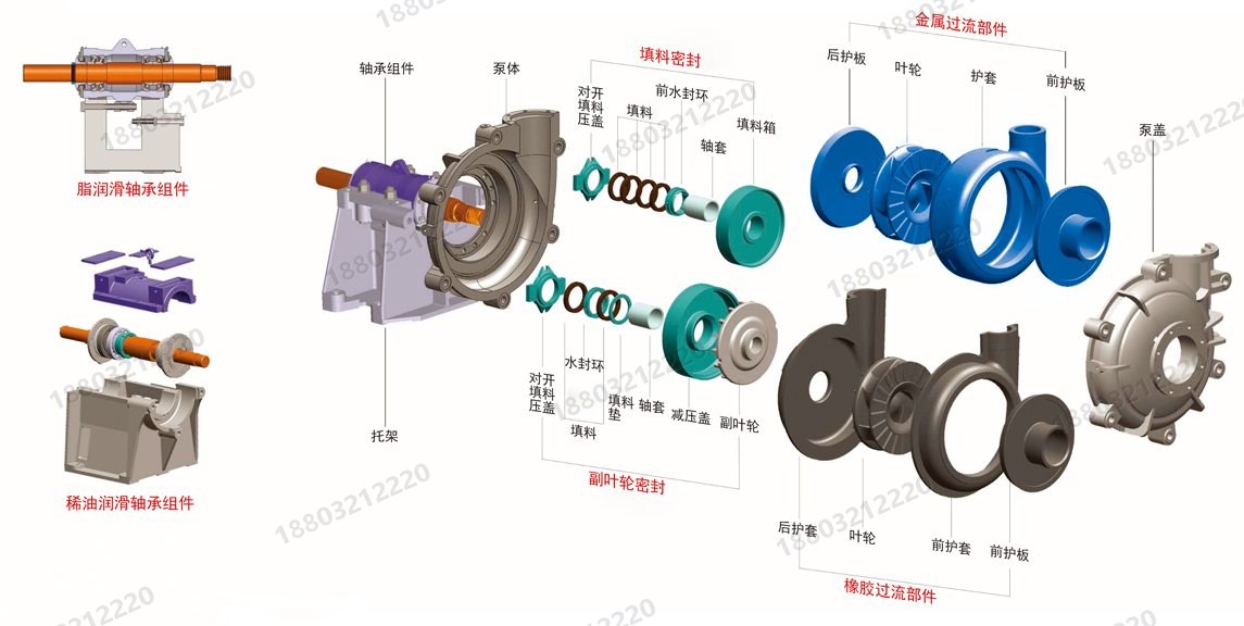
Horizontal slurry pump exploded view
Horizontal slurry pump construction
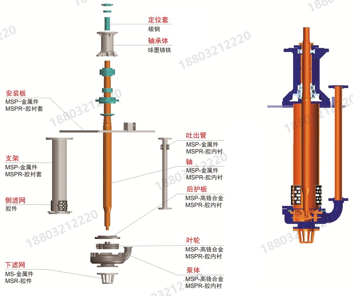
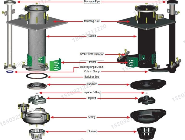
Vertical sump pump construction
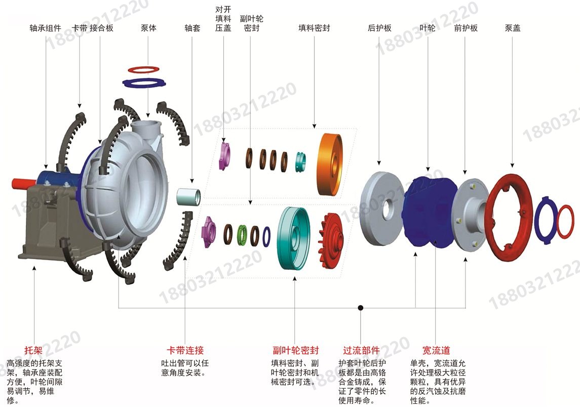
Gravel pump construction
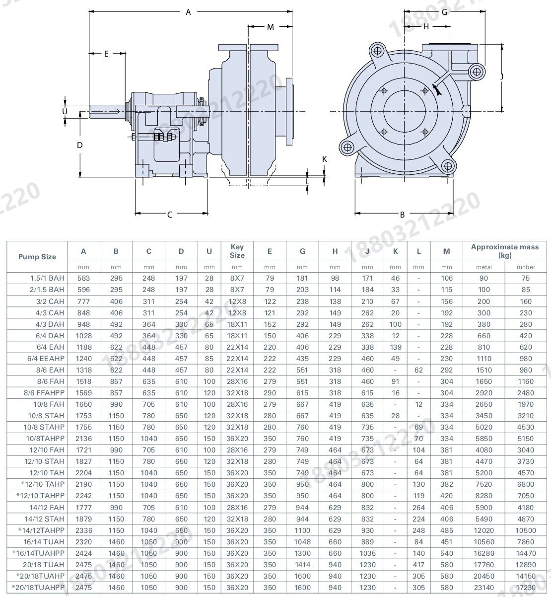
AH series installation dimensions
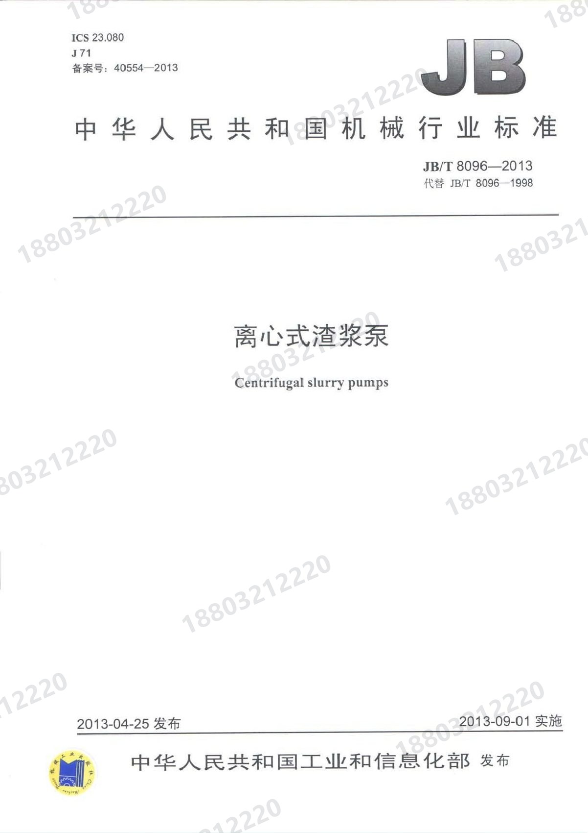
JB/T 8096-2013 centrifugal slurry pump (cover)
Metal versus rubber wetted parts

Model and spare part identification

Please provide the pump model, nameplate data and duty parameters by phone or email. Performance charts and manuals can be read online.

Click outside or press Esc to close
☎Call✉Email⇄Inquiry