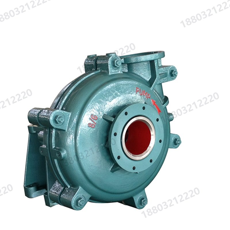
Slurry Pump Selection MethodFive inputs · five steps
Selection starts with the slurry: density, particle size, pH and line losses each change the answer. The arithmetic and the checks below can be applied directly.
Figures here come from the charts, the basic part number index and the manuals on file. Anything without a public source is marked as per supplied documents rather than inferred.
Most selection errors are input errors, not pump errors. These five items must be settled before an inquiry; miss one and the rest is guesswork.
Flow is volumetric, not gravimetric. Q (m3/h) equals mass flow (t/h) divided by slurry density (t/m3). Density follows solids SG and solids mass fraction: 1/rho = Cw/rhos + (1-Cw)/rhow. For SG 2.7 at 30% solids, rho = 1/(0.3/2.7 + 0.7/1) = about 1.23 t/m3.
Head comes from the worst case. H equals static lift plus pipe loss plus terminal pressure, with 10-15% margin. Slurry loses more head than water; important lines deserve a slurry hydraulic calculation, while rough estimates multiply clean-water loss by 1.1-1.4.
Particle size sets the construction; concentration only sets wear rate. Once maximum particle size approaches about one third of the impeller passage width, blockage risk rises sharply. Coarse angular solids call for a wide-passage single-casing pump rather than a larger version of the same one.
pH, chloride and temperature set material and seal. The same sandy water at pH 4 and pH 9 can lead to opposite material choices. Above 65 C, rubber parts and some alloys need separate confirmation.
Installation decides horizontal, vertical or submersible. Pit depth, whether a pump house exists, footprint and lifting access each eliminate half the range. These are fixed at drawing stage, and changing them later costs more than correcting a model choice.
FIVE STEPS
From duty to model in five steps
Keep the order: series first, then bore, then speed and motor.
01
Calculate Q and H: convert mass to volume flow and sketch the line for losses.
02
Pick the series: screen 13 families down to two or three on particle size, density, installation and corrosivity.
03
Fix the bore: back-calculate from a 2-3.5 m/s discharge velocity, staying low in that band for abrasive slurry.
04
Check speed, efficiency and NPSH: speed governs wear, and NPSHa must exceed NPSHr with margin.
05
Size motor and seal: maximum shaft power times 1.1-1.2, then packing, expeller or mechanical seal by suction pressure.
AFFINITY LAWS
Slowing down or trimming beats replacing
For one pump at changed speed, flow scales with speed, head with speed squared and shaft power with speed cubed. Ten percent slower gives 90% flow, 81% head and only 73% power, which is the clearest value of a VFD in slurry service.
Change
Flow
Head
Shaft power
Where it fits
Speed -10%
90%
81%
73%
Duty oversized, energy saving wanted
Impeller trimmed 5%
95%
90%
86%
Head slightly high, no VFD
Speed +10%
110%
121%
133%
Not advised: wear and cavitation rise too
Both changes move the efficiency point, so re-measure flow, head and vibration afterwards. Impeller trimming is a factory calculation; do not cut a high-chrome impeller by ratio on site.
NPSH & SEALING
Two checks that get skipped
NPSH and seal water pressure are the usual roots of vibration, flow loss and leakage after commissioning.
Keep NPSHa at least 0.5 m above NPSHr. NPSHa equals atmospheric head plus suction level head minus vapour pressure head minus suction line loss. Hotter slurry, longer suction pipes and more elbows all reduce it.
Seal water pressure must exceed casing pressure. Packing and expeller seals work on a positive water differential. Practice is 0.05-0.1 MPa above casing pressure, with flow set by stuffing box and sleeve clearance; losing water burns packing first, then the sleeve.
Staged units are calculated per stage. From stage two the inlet pressure accumulates, so seal water pressure and casing rating must be checked against the actual stage count.
COMMON MISTAKES
Five mistakes that force a re-selection
Selecting from a clean-water catalogue. Efficient zones differ; a pump picked from a water curve usually falls short on slurry.
Giving one flow point instead of a band. Duty swings between minimum and maximum; the pump should sit inside its efficient zone, not on the edge.
Confusing solids content with particle size. Dense fine slurry and dilute coarse slurry lead to opposite material choices.
Ignoring spares and service access. Wear parts are replaced on a cycle; without lifting and disassembly room, every service costs an extra day.
Sizing the motor on maximum flow. Motor power follows maximum shaft power with margin, and shaft power peaks at the high-flow end; the two are not the same number.
FAQ
Slurry Pump Selection Method: common questions
What do you need to select a pump?
Medium and solids SG, particle size distribution and maximum size, solids content, flow and head, pH and chloride, temperature, and installation type with pit depth or line length. A nameplate photo of the existing pump shortens this considerably.
Should flow and head carry margin?
Yes, but not by oversizing the pump. Add 10-15% on head and cover the flow band; excess margin means running off the efficient point, which raises both wear and energy use.
How is slurry density calculated?
1/rho = Cw/rhos + (1-Cw)/rhow, with Cw the solids mass fraction and rhos the solids SG. Volumetric concentration uses a different relation, so state which one you quote.
Can you suggest a model from experience?
A direction, yes; an order basis, no. Media vary too much. An experience-based model serves budget estimates, while firm selection needs data and a hydraulic check.
NEXT STEP
Send the model and duty; we check the part
For pumps, send medium, flow, head, density and installation. For parts, send model, frame code and basic number. We reply within one business day.