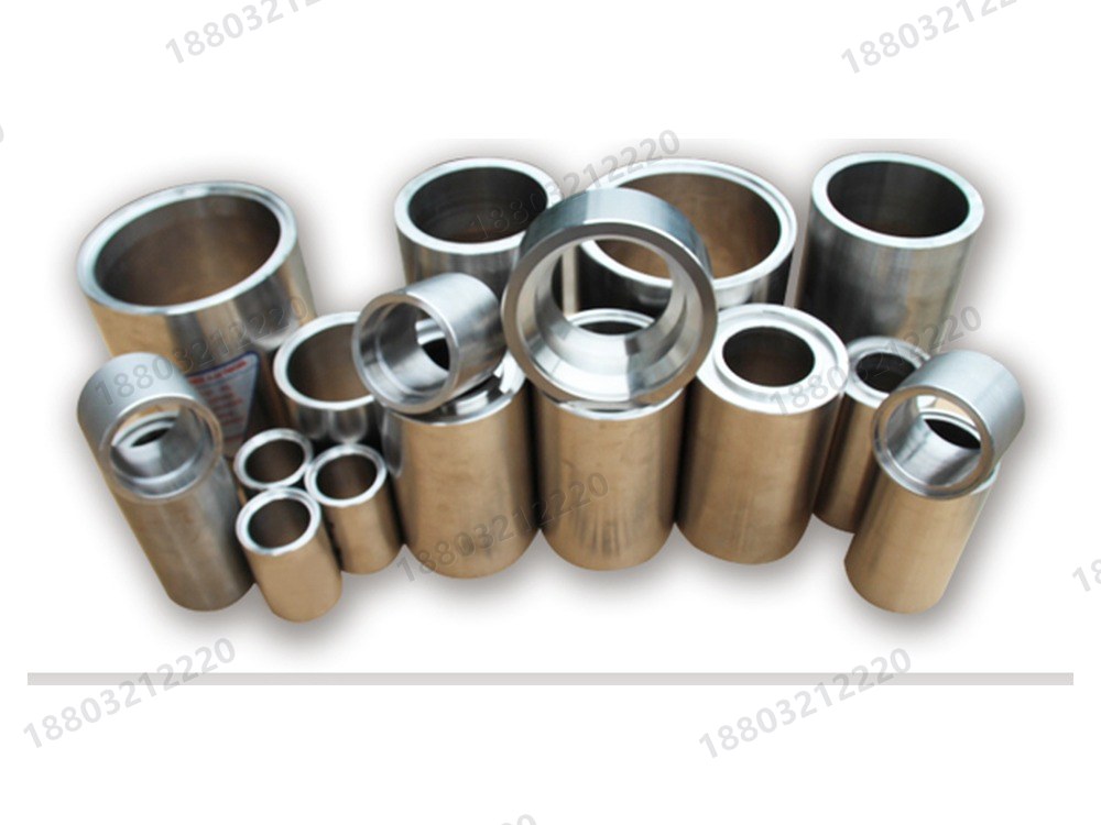
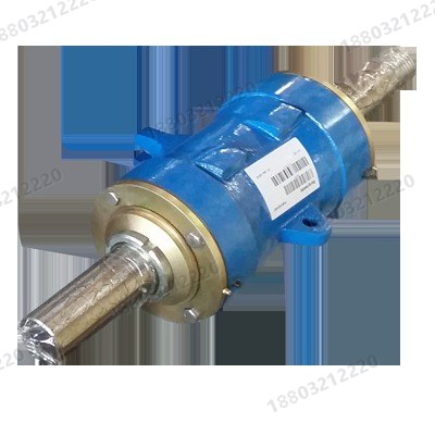
The HH series builds on the heavy duty slurry pump with thicker wear sections and heavier frames for higher single-stage head. It suits low-concentration/high-head or high-concentration/low-abrasion high-head duties, long-distance lines and series operation.
Each segment explained against published industry naming conventions.
| Field | Meaning |
|---|---|
| Suction bore | 1.5 in |
| Discharge bore | 1 in |
| Frame code | C (commonly published max. motor power about 30 kW) |
| Series code | HH |
HH Series High Head Slurry Pump
Thicker wear sections with a pump end designed for higher pressure duty.
Can be staged in series to raise total head.
Frames carry higher loads than a standard heavy duty pump of the same bore.
Wear-resistant metal wetted parts, with rotatable discharge positions.
Long-distance tailings and concentrate pipelines
Series-staged pressure boosting
High-head duties in metallurgy, chemical plants and dredging

Primarily high-chrome wear alloy; rubber or corrosion-resistant alloys are evaluated against pH, temperature and chloride content when the medium is corrosive.
Packing, expeller or mechanical seals. On high-head duty, seal-water pressure and the number of stages deserve particular attention.
Clear-water data for this model, full series charts and notes from the manuals.
| Parameter | Value / description |
|---|---|
| Suction bore | 1.5 in |
| Discharge bore | 1 in |
| Frame code | C (commonly published max. motor power about 30 kW) |
| Series code | HH |
| Construction | Horizontal, double-casing, high-head heavy duty slurry pump |
| Wetted material options | Primarily high-chrome wear alloy; rubber or corrosion-resistant alloys are evaluated against pH, temperature and chloride content when the medium is corrosive. |
| Shaft seal options | Packing, expeller or mechanical seals. On high-head duty, seal-water pressure and the number of stages deserve particular attention. |
| Published series coverage | Typical coverage: discharge bores about 25-150 mm and single-stage head up to roughly 90-118 m. |
| Model | Max. power kW | Q m³/h | Q L/s | H m | n r/min | Max. eff. % | NPSH m | Impeller mm |
|---|---|---|---|---|---|---|---|---|
| 1.5/1C-HH | 30 | 16.2-34.2 | 4.5-9.5 | 25-92 | 1400-2200 | 20 | 2-5.5 | 330 |
Complete clear-water performance data for this series. Click to expand; tables scroll horizontally.
| Model | Max. power kW | Q m³/h | Q L/s | H m | n r/min | Max. eff. % | NPSH m | Impeller mm |
|---|---|---|---|---|---|---|---|---|
| 1.5/1B-AH | 15 | 12.6-28.8 | 3.5-8 | 6-68 | 1200-3800 | 40 | 2-4 | 152 |
| 2/1.5B-AH | 15 | 32.4-72 | 9-20 | 6-58 | 1200-3200 | 45 | 3.5-8 | 184 |
| 3/2C-AH | 30 | 39.6-86.4 | 11-24 | 12-64 | 1300-2700 | 55 | 4-6 | 214 |
| 4/3C-AH | 30 | 86.4-198 | 24-55 | 9-52 | 1000-2200 | 71 | 4-6 | 245 |
| 4/3D-AH | 60 | 86.4-198 | 24-55 | 9-52 | 1000-2200 | 71 | 4-6 | 245 |
| 6/4D-AH | 60 | 162-360 | 45-100 | 12-56 | 800-1550 | 65 | 5-8 | 365 |
| 6/4E-AH | 120 | 162-360 | 45-100 | 12-56 | 800-1550 | 65 | 5-8 | 365 |
| 8/6E-AH | 120 | 360-828 | 100-230 | 10-61 | 500-1140 | 72 | 2-9 | 510 |
| 8/6R-AH | 300 | 360-828 | 100-230 | 10-61 | 500-1140 | 72 | 2-9 | 510 |
| 10/8ST-AH | 560 | 612-1368 | 170-380 | 11-61 | 400-850 | 71 | 4-10 | 686 |
| 12/10ST-AH | 560 | 936-1980 | 260-550 | 7-68 | 300-800 | 82 | 6 | 762 |
| 14/12ST-AH | 560 | 1260-2772 | 350-770 | 13-63 | 300-600 | 77 | 3-10 | 965 |
| 16/14TU-AH | 120 | 1368-3060 | 380-850 | 11-63 | 250-550 | 79 | 4-10 | 1067 |
| 20/18TU-AH | 1200 | 2520-5400 | 700-1500 | 13-57 | 200-400 | 85 | 5-10 | 1370 |
| 1.5/1B-AH | 15 | 10.8-25.2 | 3-7 | 7-52 | 1400-3400 | 35 | 2-4 | 152 |
| 2/1.5B-AH | 15 | 25.2-54 | 7-15 | 5.5-41 | 1000-2600 | 50 | 2.5-5 | 178 |
| 3/2C-AH | 30 | 36-75.6 | 10-21 | 13-39 | 1300-2100 | 55 | 2-4 | 213 |
| 4/3C-AH | 30 | 79.2-180 | 22-50 | 5-34.5 | 800-1800 | 59 | 3-5 | 245 |
| 4/3D-AH | 60 | 79.2-180 | 22-50 | 5-34.5 | 800-1800 | 59 | 3-5 | 245 |
| 6/4D-AH | 60 | 144-324 | 40-90 | 12-45 | 800-1350 | 65 | 3-5 | 365 |
| 6/4E-AH | 120 | 144-324 | 40-90 | 12-45 | 800-1350 | 65 | 3-5 | 365 |
| 8/6E-AH | 120 | 324-720 | 90-200 | 7-49 | 400-1000 | 65 | 5-10 | 510 |
| 8/6R-AH | 300 | 324-720 | 90-200 | 7-49 | 400-1000 | 65 | 5-10 | 510 |
| 10/8ST-AH | 560 | 540-1188 | 150-330 | 12-50 | 400-750 | 75 | 4-12 | 686 |
| 12/10ST-AH | 560 | 720-1620 | 200-450 | 7-45 | 300-650 | 80 | 2.5-7.5 | 762 |
| 14/12ST-AH | 560 | 1152-2520 | 320-700 | 13-44 | 300-500 | 79 | 3-8 | 965 |
| 16-14TU-AH | 1200 | 1224-2754 | 340-765 | 9-43 | 250-450 | 82 | 3-8 | 1067 |
| 20-18TU-AH | 1200 | 2268-4860 | 630-1350 | 11-46 | 200-350 | 82 | 2-8 | 1372 |
| 10/8E-M | 120 | 540-1440 | 150-400 | 14-60 | 600-1000 | 73 | 4-10 | 549 |
| 10/8R-M | 300 | 540-1440 | 150-400 | 14-60 | 600-1000 | 73 | 4-10 | 549 |
| 1.5/1C-HH | 30 | 16.2-34.2 | 4.5-9.5 | 25-92 | 1400-2200 | 20 | 2-5.5 | 330 |
| 3/2D-HH | 60 | 68.4-136.8 | 19-38 | 25-87 | 850-1400 | 47 | 3-7.5 | 457 |
| 4/3E-HH | 120 | 126-252 | 35-70 | 12-97 | 600-1400 | 50 | 2-5 | 508 |
| 6/4F-HH | 260 | 324-720 | 90-200 | 30-118 | 600-1000 | 64 | 3-8 | 711 |
| 8/6S-HH | 560 | 468-1008 | 130-280 | 20-94 | 500-1000 | 65 | 4-12 | 711 |
Compiled from the AH / L / G, SP, ZJ and ZGB pump manuals, with links to the full texts.
Horizontal slurry pumps are overhung centrifugal pumps for abrasive or corrosive slurry, widely used in metallurgy, mining, petrochemical, coal, power, dredging, building materials and municipal works. Families cover heavy duty (AH, HH), light duty (L), gravel / dredging (D, G) and rubber-lined (AHR, LR, MR) builds. Pumps may be staged in series within the allowable working pressure.
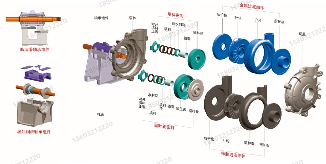
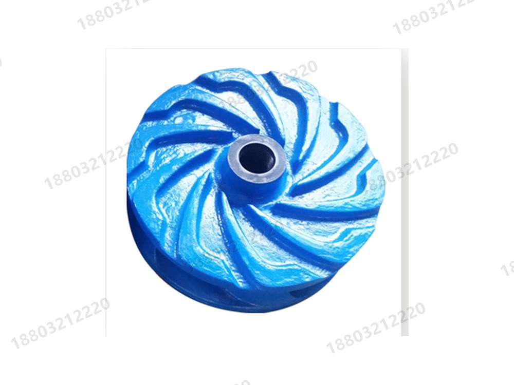
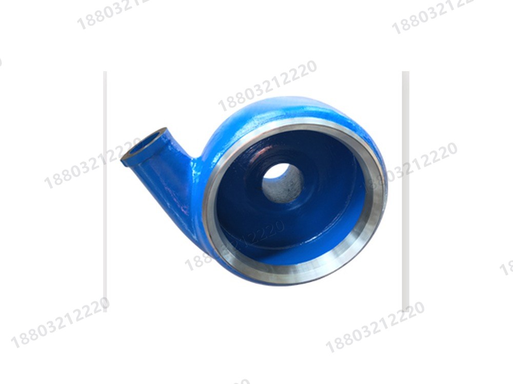
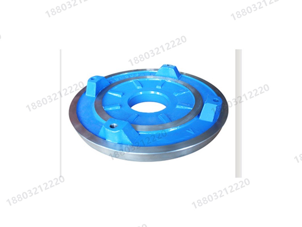
Heavy duty AH and HH pumps use a double casing: an outer pressure-retaining casing and cover in grey or ductile iron, vertically split and bolted, plus replaceable wear liners (impeller, volute liner, throat bush and frame plate liner) in metal or rubber. The discharge can be rotated in eight positions at 45 degree intervals. D and G gravel pumps use a single casing with all wetted parts in wear-resistant metal. Apart from the wet end, all horizontal types share the same frame and bearing assembly, with a large-diameter shaft and short overhang.
Preheat bearing inner rings to no more than 120 C during assembly and seat them firmly against the shaft shoulder or grease retainer. Inner rings, outer rings and spacers of double-row tapered roller bearings form a matched set and must not be interchanged. Wet-end assembly order: seals, frame plate liner with its locating nuts, impeller, volute liner clamped in place, then throat bush and cover plate. Lift crated pumps by the marked sling points without shock or excessive tilt; lifting eyes on the casing are for dismantling the casing only, never for lifting the complete pump.
Three shaft seal arrangements are common: expeller, packed gland and mechanical seal. The expeller seal suits single-stage pumps (or the first stage of a series set) where inlet positive pressure is below 10 percent of discharge pressure; it needs no seal water and does not dilute the slurry. A packed gland is simple to service but requires seal water. A mechanical seal gives the best sealing and requires cooling water. A packed gland comprises the stuffing box, shaft sleeve, spacer, O-rings, packing, packing spacer, lantern ring and gland. Bearings are grease or oil lubricated, with oil lubrication preferred for high temperature or large pumps.
Before start-up check that foundation and coupling bolts are tight, turn the shaft by hand in the direction of rotation without rubbing, verify motor rotation against the arrow on the casing, and align the V-belts square to the pulleys. Starting on clean water is preferable before slurry is introduced. During operation watch the instruments for flow, velocity and current and correct any abnormality. Where possible flush with clean water before stopping, then stop the pump before closing the valve. For vertical sump pumps, turn on the guide bearing flush water five minutes before starting and close it five minutes after stopping.
Check impeller-to-throatbush clearance, bearing temperature and lubrication, seal water pressure and flow, and wear of wetted parts on a regular basis. A worn impeller reduces flow and head and raises vibration and noise, so adjust the clearance or replace the wear parts. Typical faults are insufficient flow or head, bearing overheating, vibration, seal leakage and cavitation, usually caused by blockages, wrong rotation, low speed, air ingress on the suction side, inadequate NPSH or loss of dynamic balance. Record basic part numbers and material suffixes and verify them against the pump model and supplied documents.
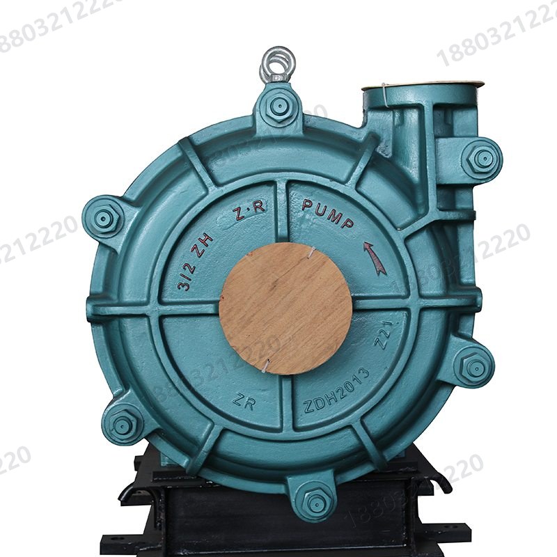
HH pumps suit low-concentration high-head slurry or high-concentration mildly abrasive high-head slurry. They share the double-casing heavy duty construction and drive end with the AH series.
Pumps may be staged in series within the maximum allowable working pressure; seal water pressure must be checked for each stage.
Extracts from the original manuals are shown in the Chinese edition; the full texts are available via the links below.
Open each part page for function, material and replacement notes.
Models, parts and manuals related to this product.
Send the model or worn-part dimensions, or call +86 188 0321 2220 / email sale@pumpq.com.
We reply within one business day. You can also call +86 188 0321 2220.
Please provide the pump model, nameplate data and duty parameters by phone or email. Performance charts and manuals can be read online.